F-22 RAPTOR RC AIRCRAFT
Why I Built This
Project motivation and objectives
This started as a stubborn childhood dream I couldn't afford back then. Now I'm giving that kid what he always wanted, but building it myself instead of pulling a perfect toy out of a box.
Part nostalgia, part challenge. The more you fuck around, the more you found out. Simple goal: bring a dream to life with my own hands and watch it soar.
Tools
Required equipment and instruments
Cutting Tools
Utility knife, Scissors, Pliers
Measuring Tools
Ruler, Measuring Tape
Assembly Tools
Glue gun, Soldering iron, Screwdrivers
Materials
Complete bill of materials
Airframe Materials
- MPPF Board
- Push Rods
- Carbon Fiber Rods
- Control Horns
- Linkage Stopper
- Servo Mounts
- 5045 Propeller
Adhesives & Finishing
- Hot Glue
- Super glue
- Masking Tape
- Spray Paint (Optional)
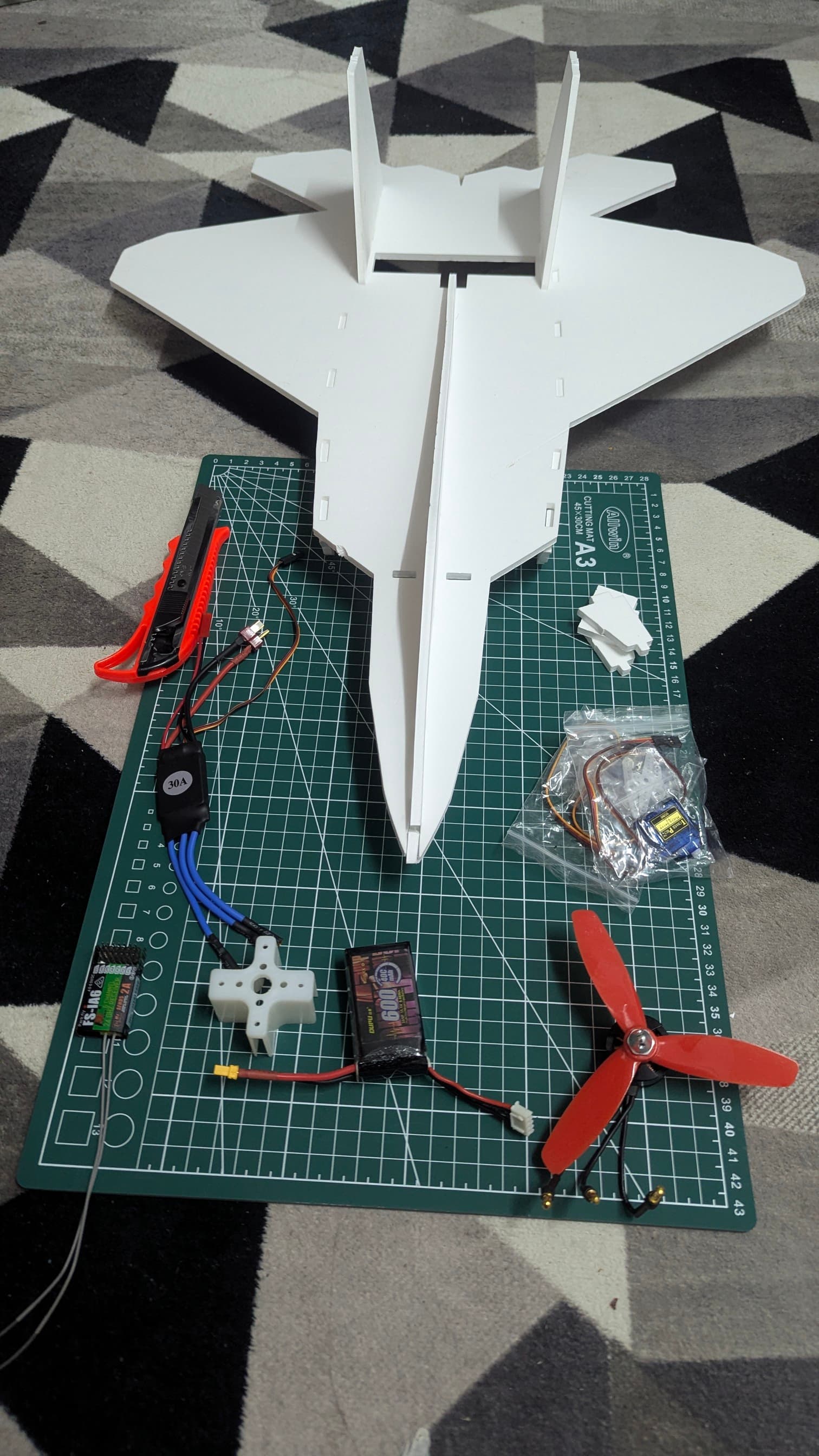
Electronics
Avionics and control systems
Required Components
- ESC (Electronic Speed Controller)
- 1806/2280kv Brushless Motor
- FlySky FS-i6 Transmitter
- FlySky FS-iA6 Receiver
- 9G Servo Motors (x2)
- 3S 600mAh 40C LiPo Battery
Plans
Technical drawings and specifications
Download links: Google Drive Folder
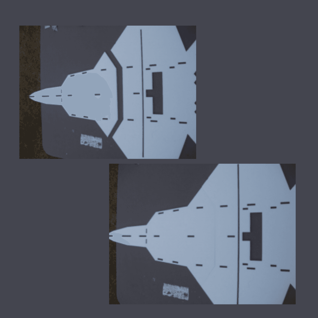
CAD Images
3D models and renderings
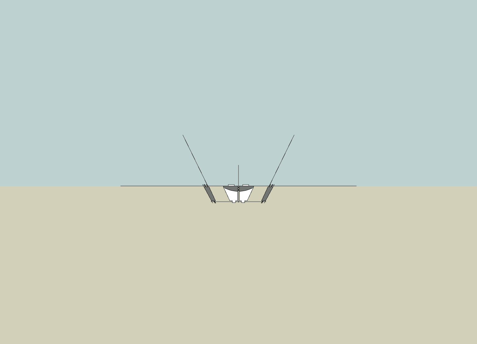
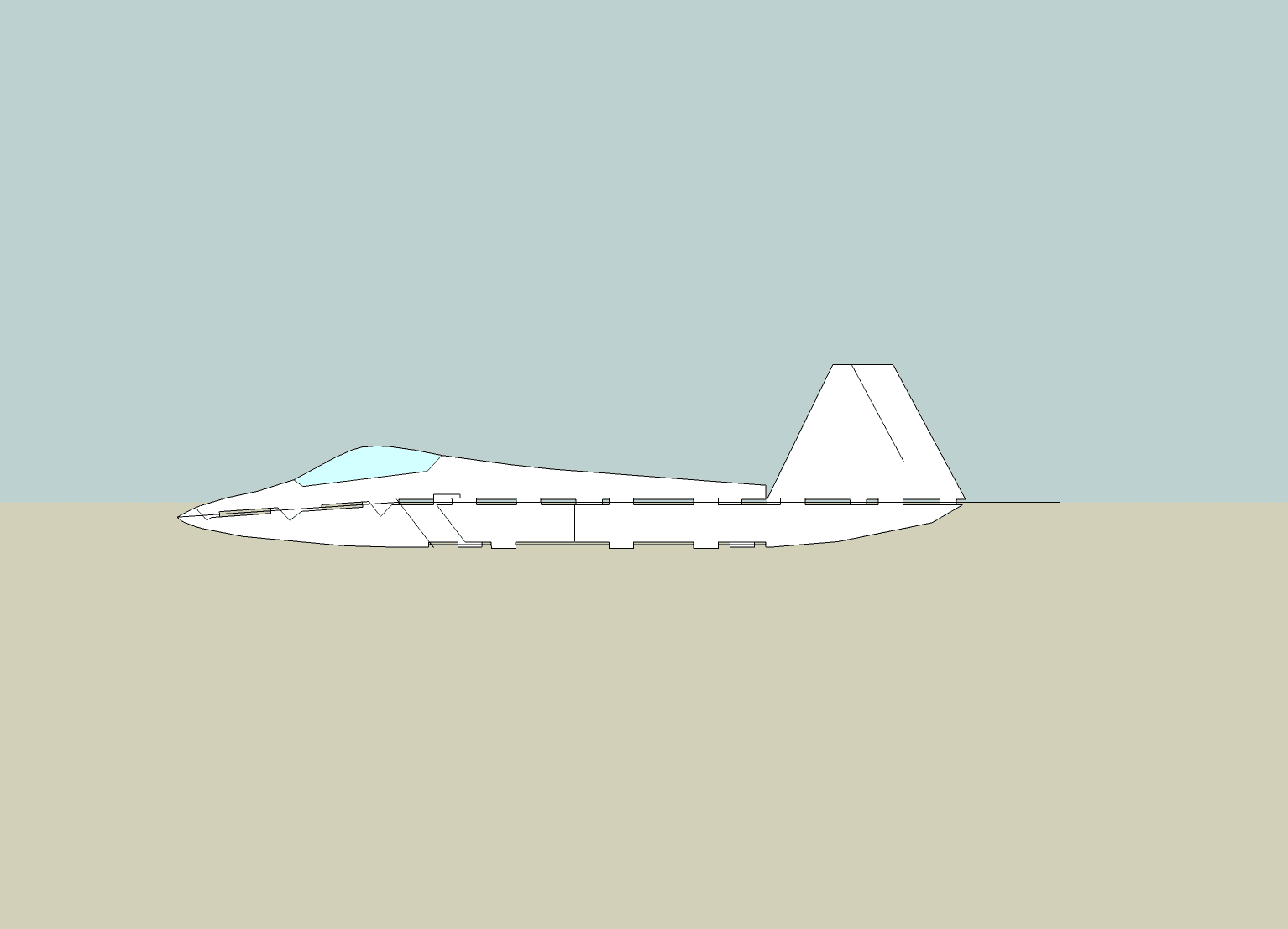
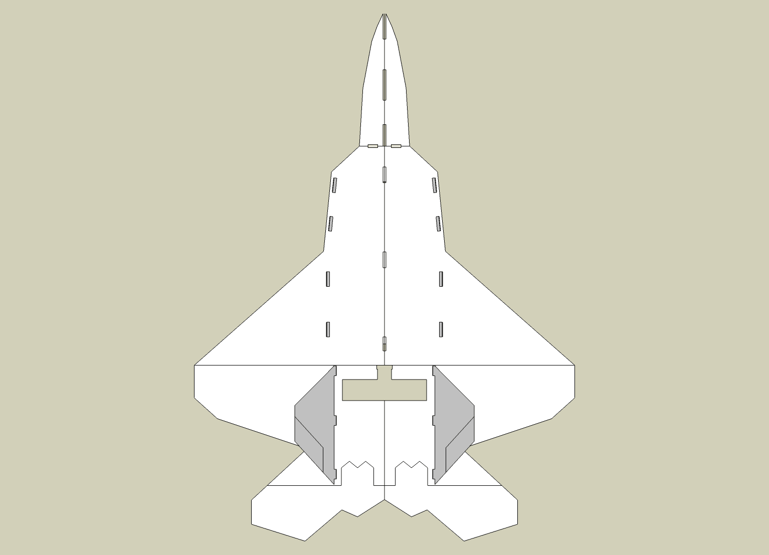
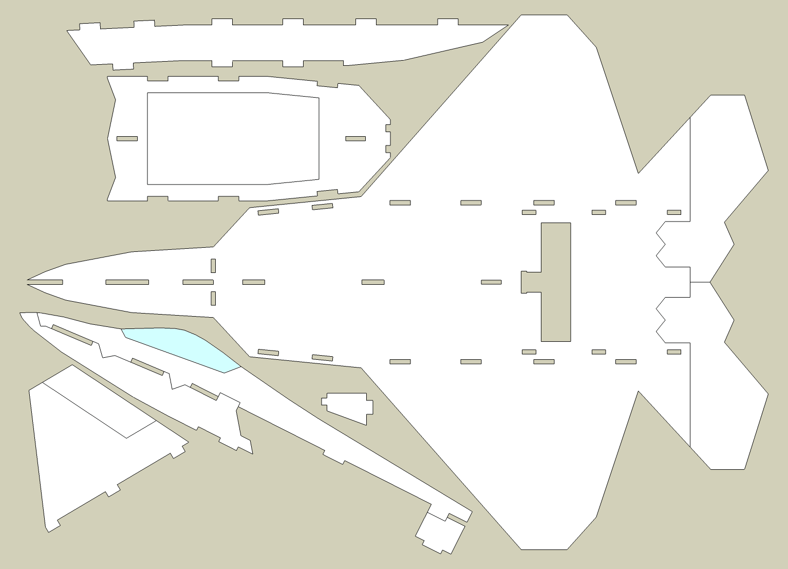
Computer-aided design models and technical renderings of the F-22 Raptor build.
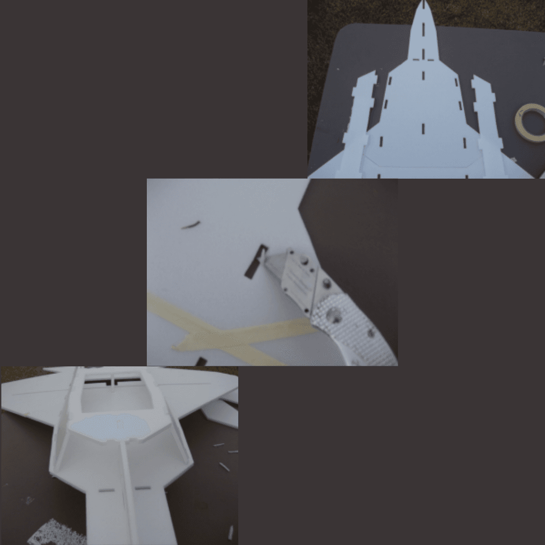
Build Process
Step-by-step construction guide
You can download and see the full guide here: Quick Build F-22 Guide (PDF)
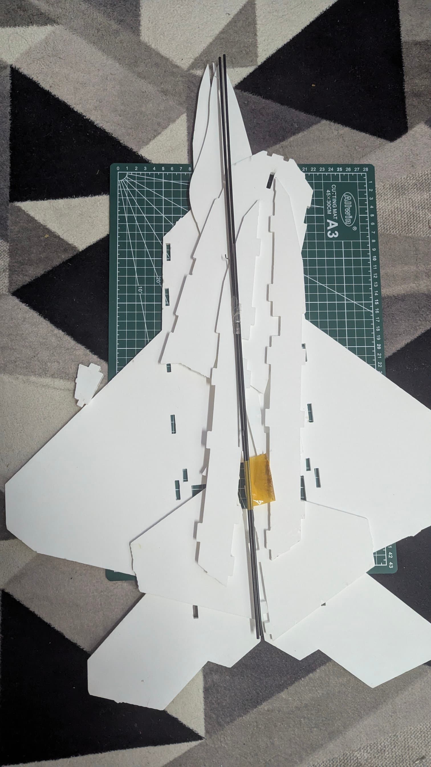
STEP 1: Install the Carbon Wing Spar
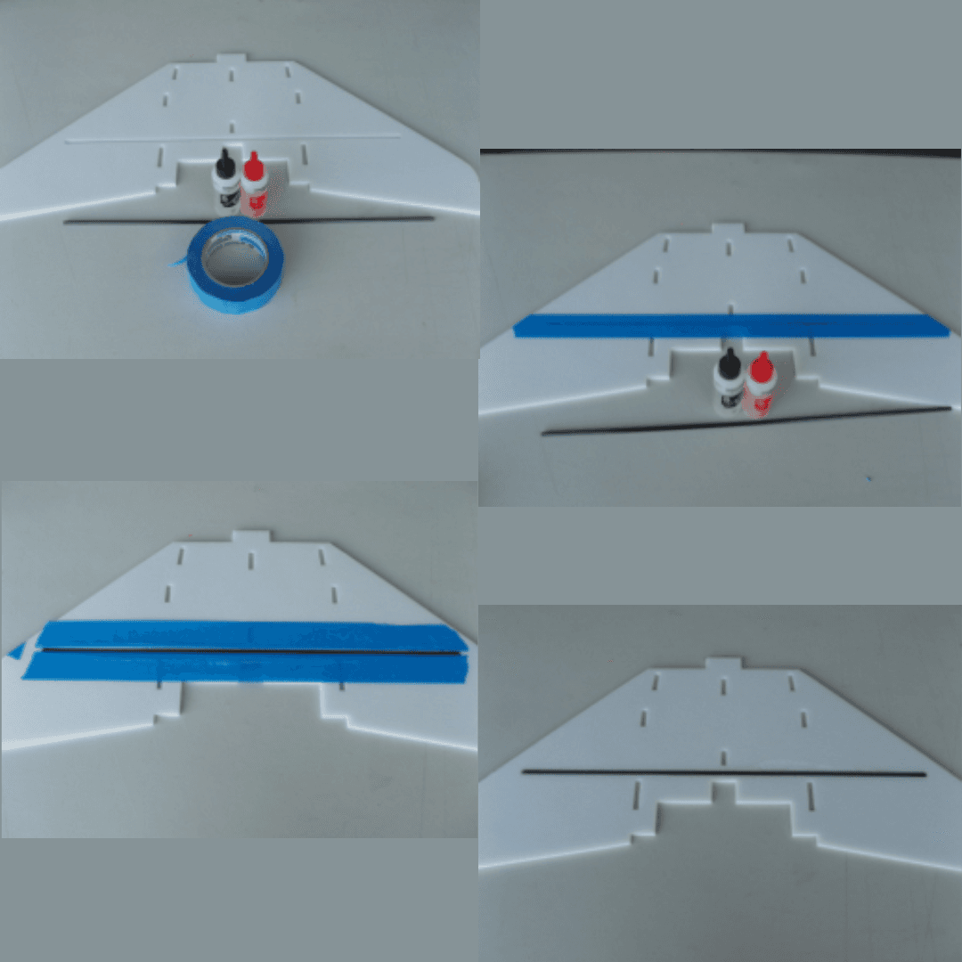
- Mask the spar slot on top and bottom of the wing to protect the foam surface.
- Test-fit the carbon rod to ensure it slides smoothly into the slot without force.
- Mix epoxy thoroughly following the manufacturer's instructions for proper cure.
- Pour epoxy into the slot (rod not inserted yet) ensuring even coverage along the entire length.
- Insert rod, press down, wipe excess epoxy from the surface immediately with a paper towel.
- Remove tape after a few minutes—don't glue the wing to the table! This prevents the epoxy from bonding the wing to your work surface.
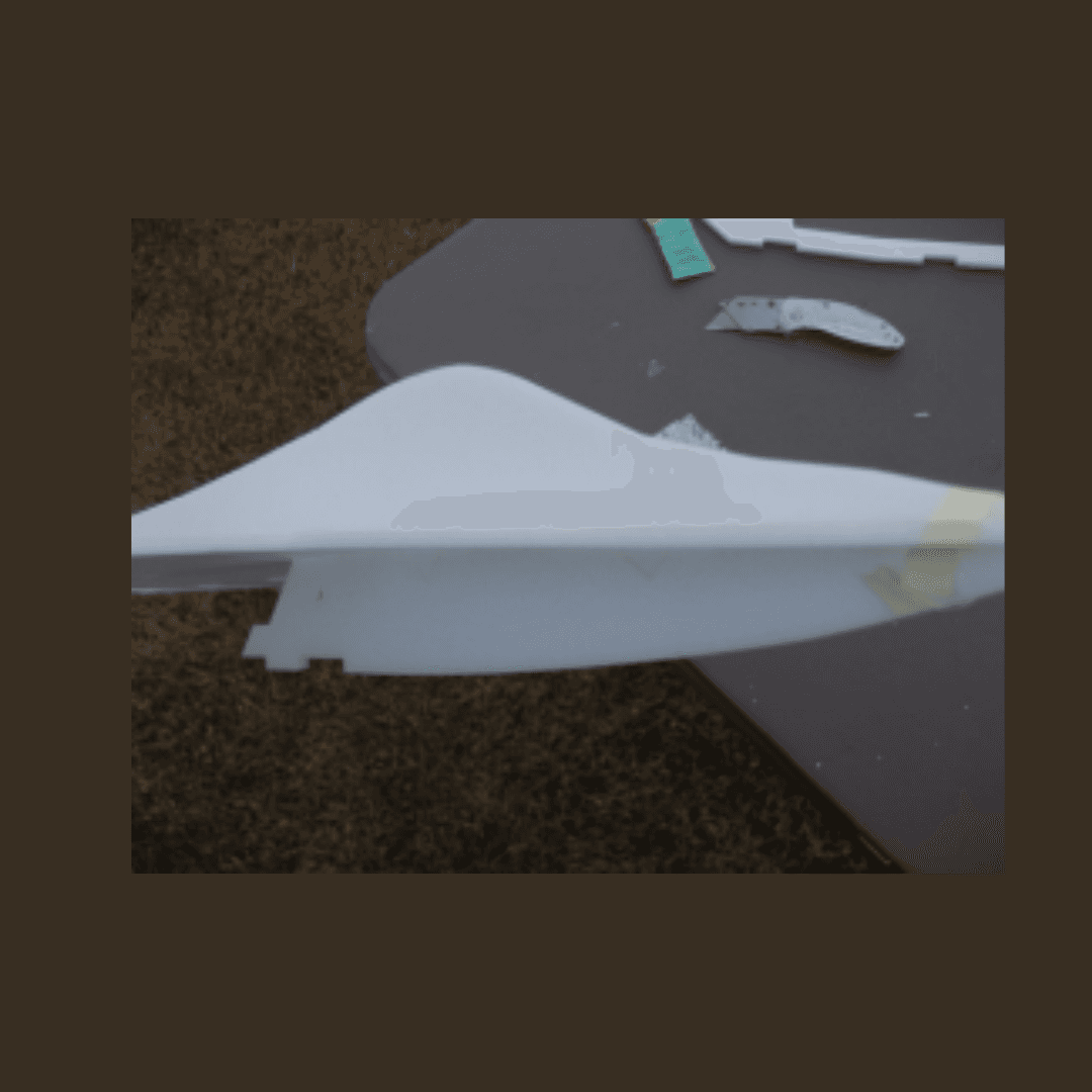
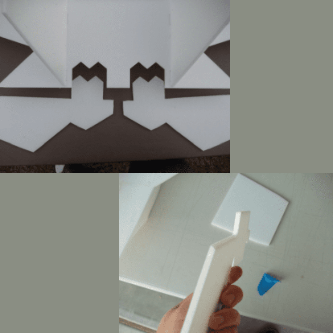
STEP 2: Build the Front Fuselage
- Align the two front fuse pieces carefully to ensure a proper fit.
- Apply epoxy to the joint using an even coat along the mating surfaces.
- Press together firmly to create a strong bond.
- Keep it straight while curing to avoid any warping or misalignment.
- Make sure it's not stuck to the table by using wax paper or a release surface.
STEP 3: Install Canopy + Forward Lower Fuse
- Identify canopy (top) and lower fuse (bottom) pieces before installation.
- Insert both into their slots on the wing to verify proper fit.
- Glue using foam-safe glue to avoid melting the foam material.
- Align canopy with wing surface for a flush, aerodynamic finish.
- Let glue set completely before handling.
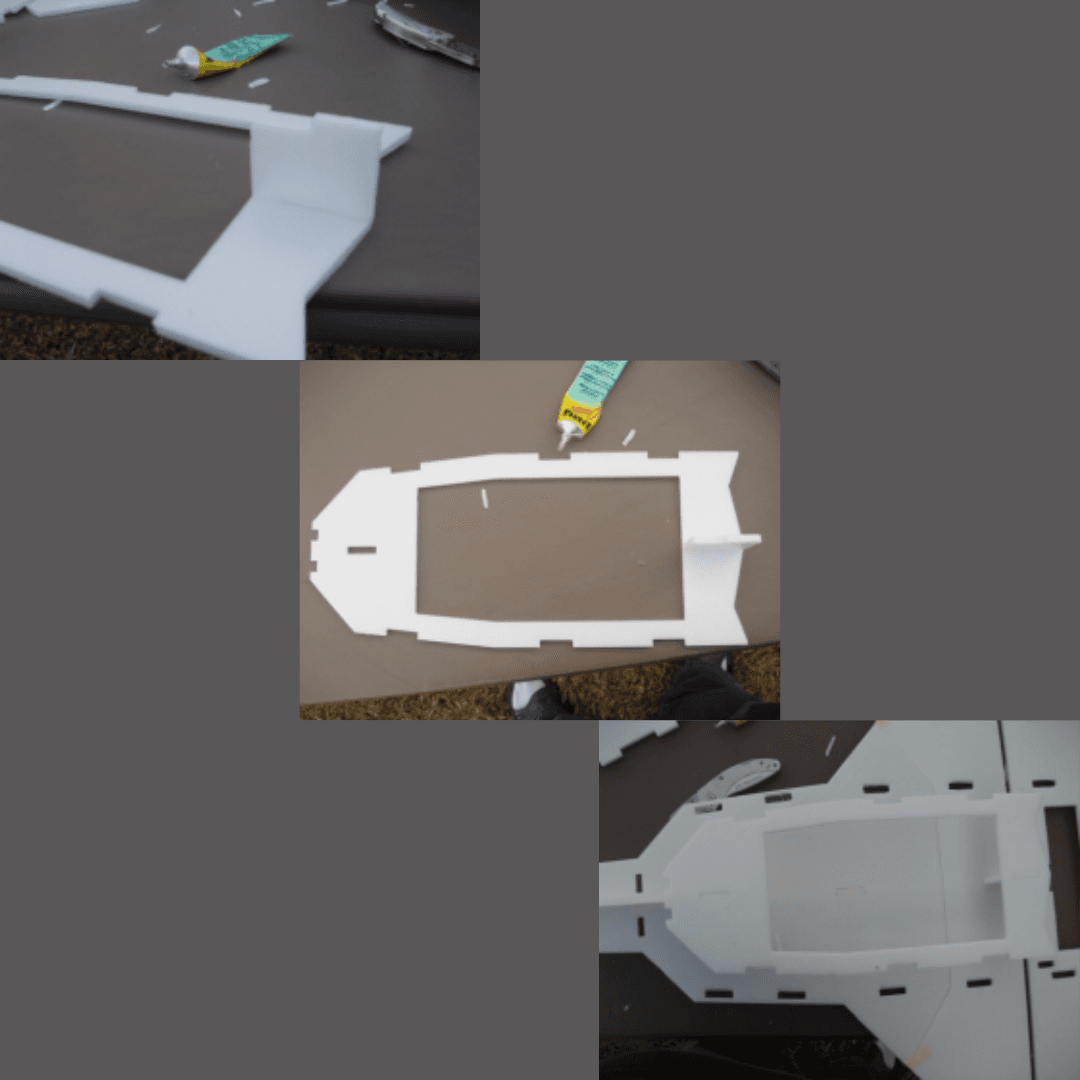
STEP 4: Attach the Bottom Fuselage
- Find the small bridging piece that connects the wing and bottom fuselage.
- Glue it between wing and bottom-fuse gap to create a solid connection point.
- Attach the full bottom fuselage piece to the bridging section.
- Center it properly to maintain symmetry.
- Leave it floating—alignment gets fixed later during final assembly.
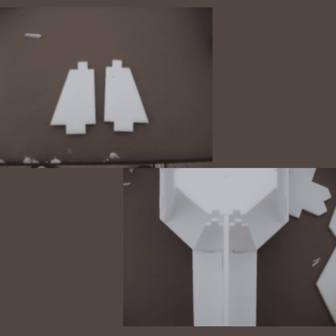
STEP 5: Install Side Engine Intakes
- Test-fit both intake pieces to check alignment.
- Trim wing slots so intakes can angle inward for proper F-22 aesthetics.
- Dry-fit with tape until symmetrical to ensure both sides match.
- Glue each intake to wing + bottom fuse for a secure attachment.
- Trim tabs protruding through the top for a clean finish.
STEP 6: Install Front Intakes
- Test-fit both pieces to verify proper placement.
- Trim edges for correct inward angle to match the design.
- Align both sides evenly for symmetrical appearance.
- Glue in place using foam-safe adhesive.
- Let dry completely before moving to the next step.
STEP 7: Mount Vertical Tails
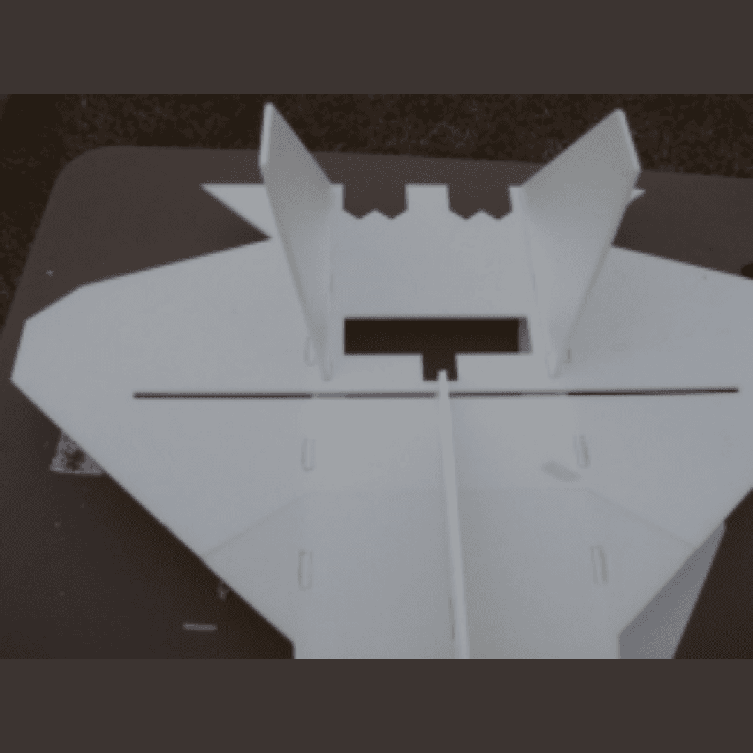
- Insert fins into top slots to check the fit.
- Trim foam to allow outward angle for the characteristic F-22 tail cant.
- Match angle with the side intakes to maintain consistent geometry.
- Glue (epoxy recommended) for maximum strength.
- Ensure both fins angle similarly for balanced flight characteristics.
STEP 8: Build & Fit the Hatch
- Take hatch piece + scrap foam for reinforcement.
- Add supports using scrap pieces to strengthen the hatch.
- Choose attachment method: velcro, magnets, tape based on your preference.
- Test-fit for snug closure to prevent it from opening in flight.
- Ensure easy removal for battery and electronics access.
STEP 9: Install Motor Mount
- Laminate plywood disc + foam disc with epoxy to create a strong mount.
- Align the combined mount on nose area ensuring proper motor alignment.
- Glue using epoxy for a permanent, strong bond.
- Hold straight while curing to prevent thrust misalignment.
- Clean any squeeze-out for a professional finish.
STEP 10: Prepare Tailerons (Elevons)
- Bevel hinge edge for free movement to allow full control surface deflection.
- Tape-hinge each taileron to the body using clear packing tape.
- Sand if the two tailerons touch in the center to prevent binding.
- Check full travel range to ensure adequate control authority.
- Make sure hinge line is clean for smooth operation.
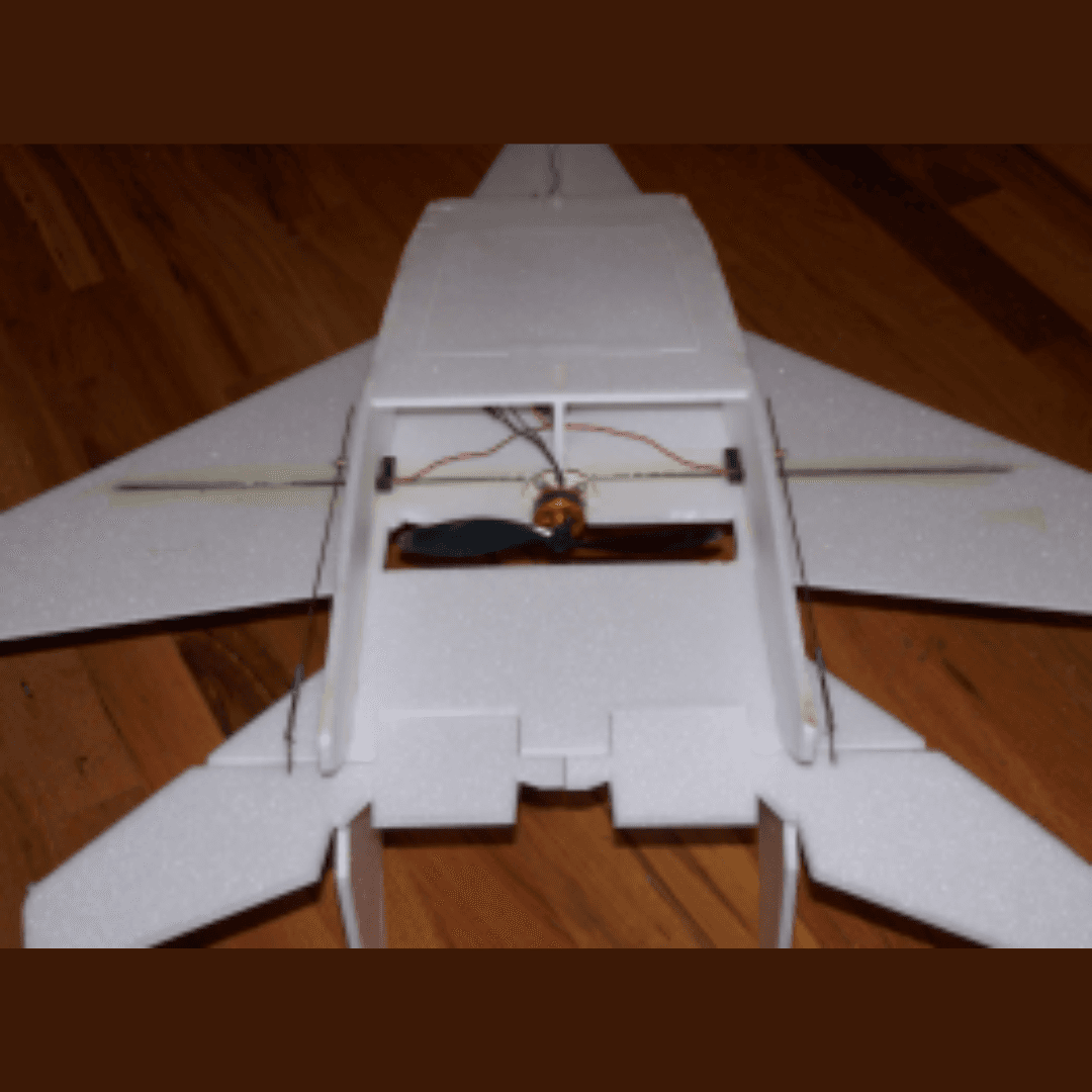
STEP 11: Install Servos + Linkages

- Cut servo pockets under the wing for recessed servo mounting.
- Glue servos above the carbon spar for structural support.
- Install control horns on tailerons at the recommended distance from hinge line.
- Connect pushrods between servos and control horns.
- Ensure smooth, binding-free movement throughout the entire range.
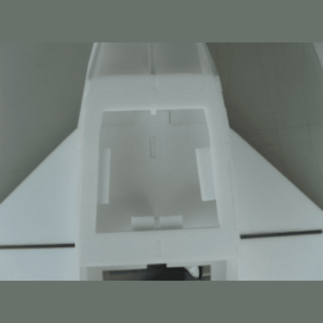
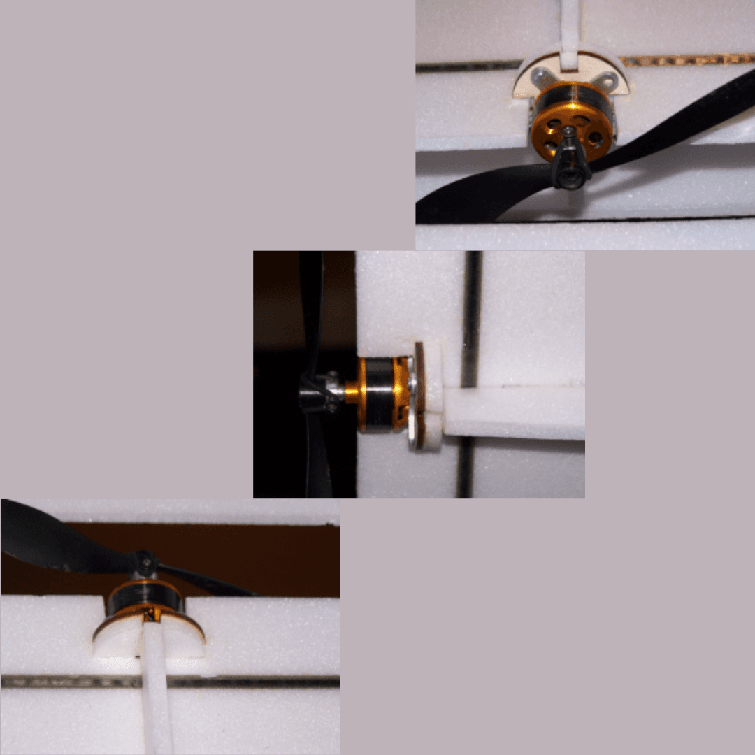
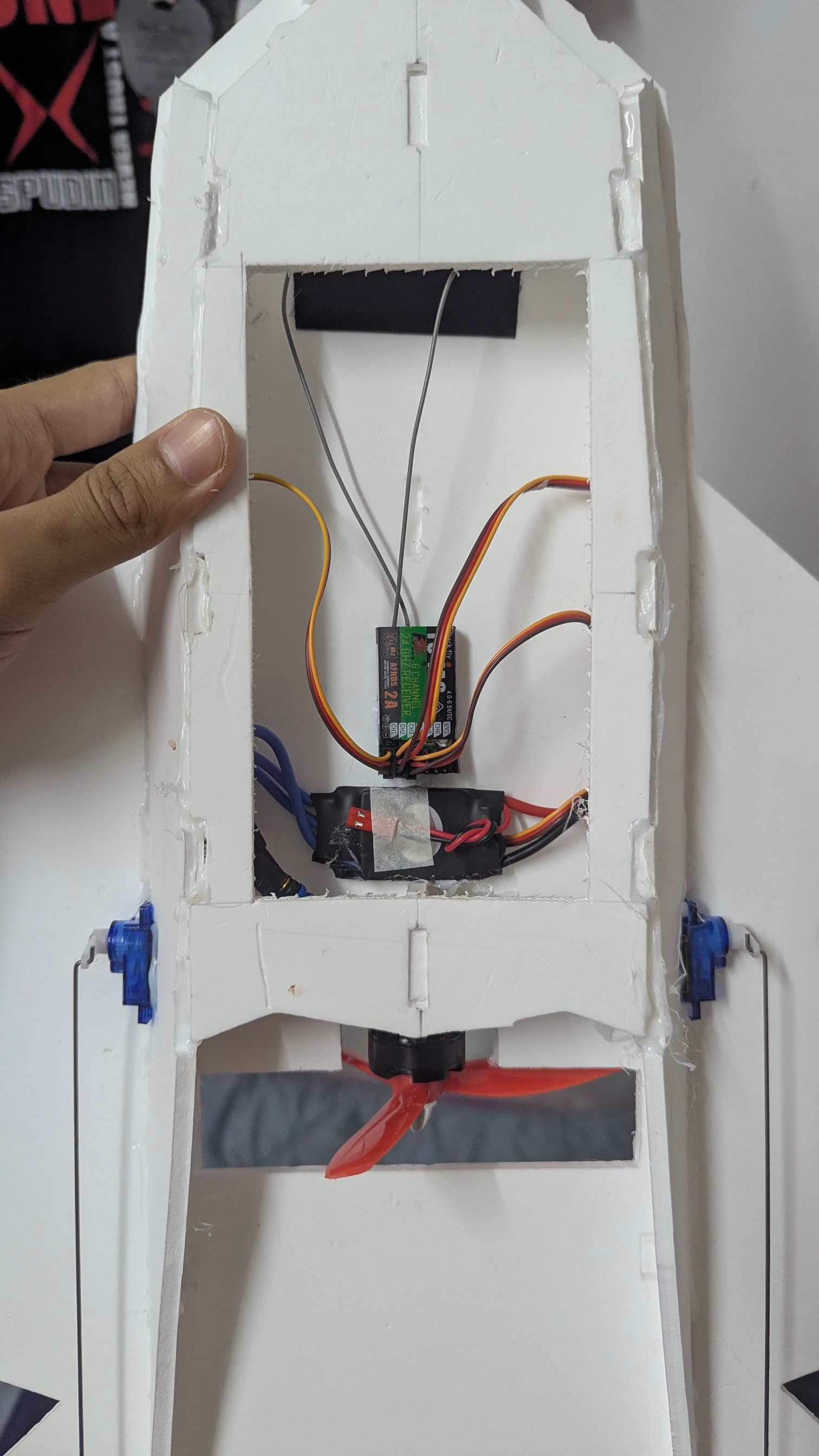
STEP 12: Install Electronics
- Mount ESC near airflow path for adequate cooling.
- Install receiver inside fuselage cavity protected from elements.
- Route servo wires cleanly to avoid interference with moving parts.
- Mount motor + prop securely to the motor mount.
- Confirm motor spins the correct direction for proper thrust.
STEP 13: Paint & Finish
- (Optional) Spray Minwax Poly for foam protection to seal the surface.
- Mask edges for clean patterns using painter's tape.
- Use foam-safe paint (or test first) to avoid melting the foam.
- Spray multiple light coats rather than one heavy coat.
- Let everything cure fully before handling or flying.
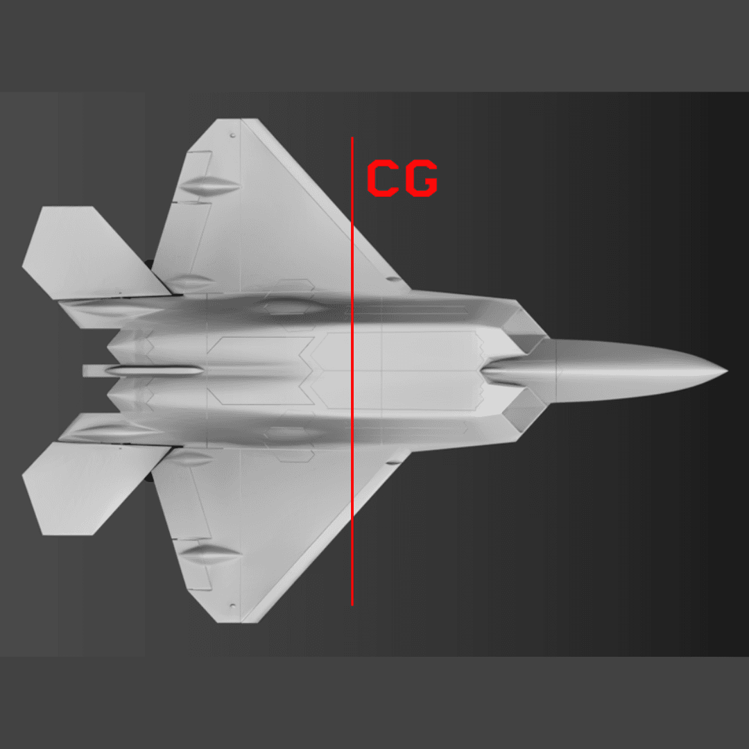
STEP 14: Set Center of Gravity
- CG = 3.25 inches behind wing break for optimal flight characteristics.
- Position battery to achieve balance by moving it forward or backward.
- Hold plane at CG points with your fingers to test balance.
- Adjust until balanced level with no nose-up or nose-down tendency.
- Mark battery location for consistent placement before each flight.
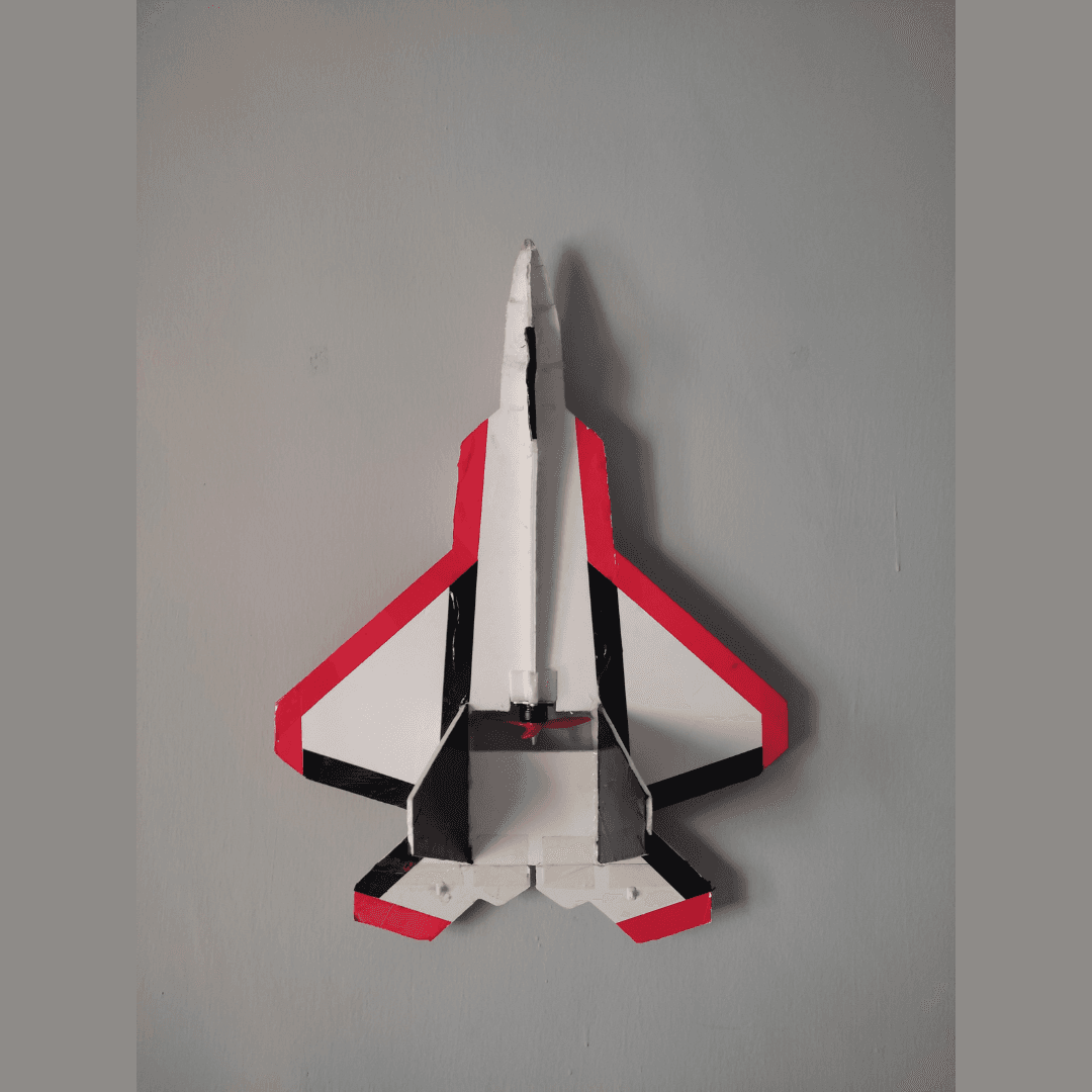
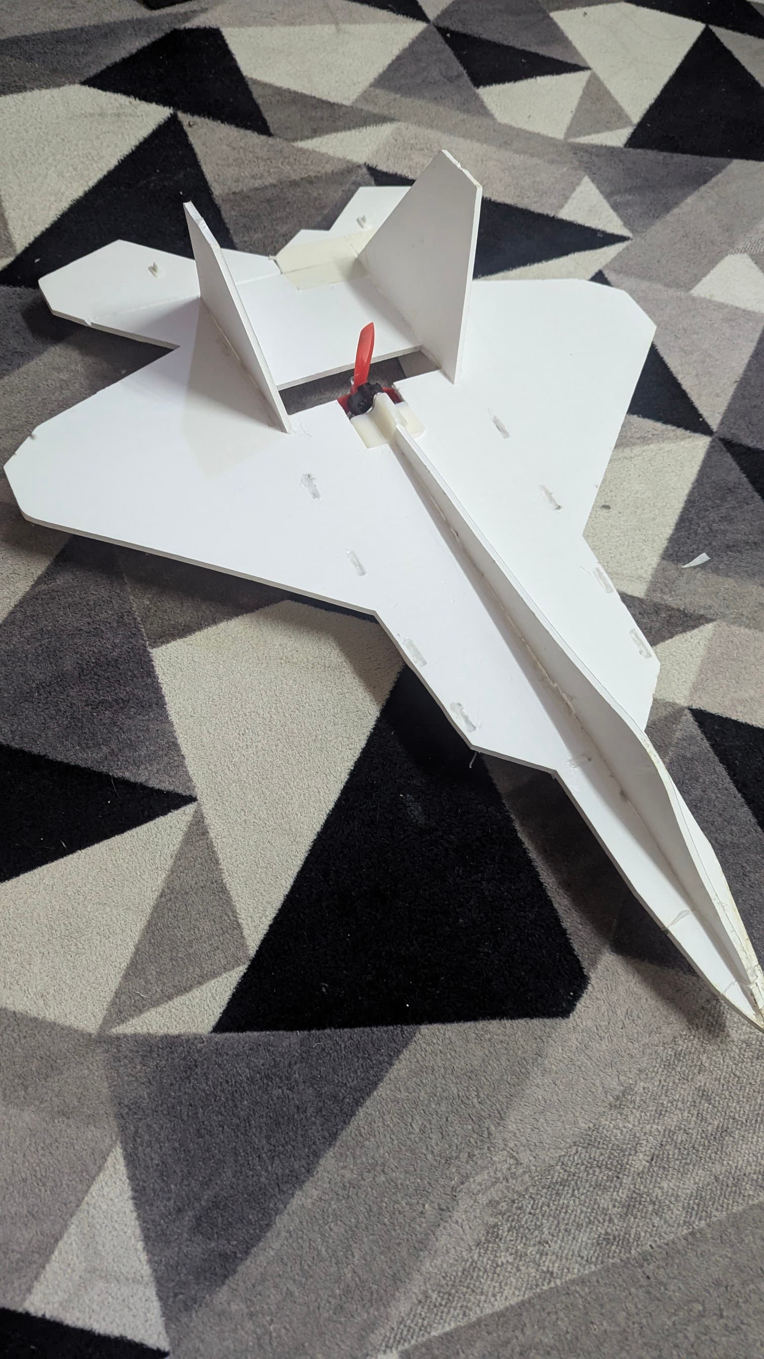
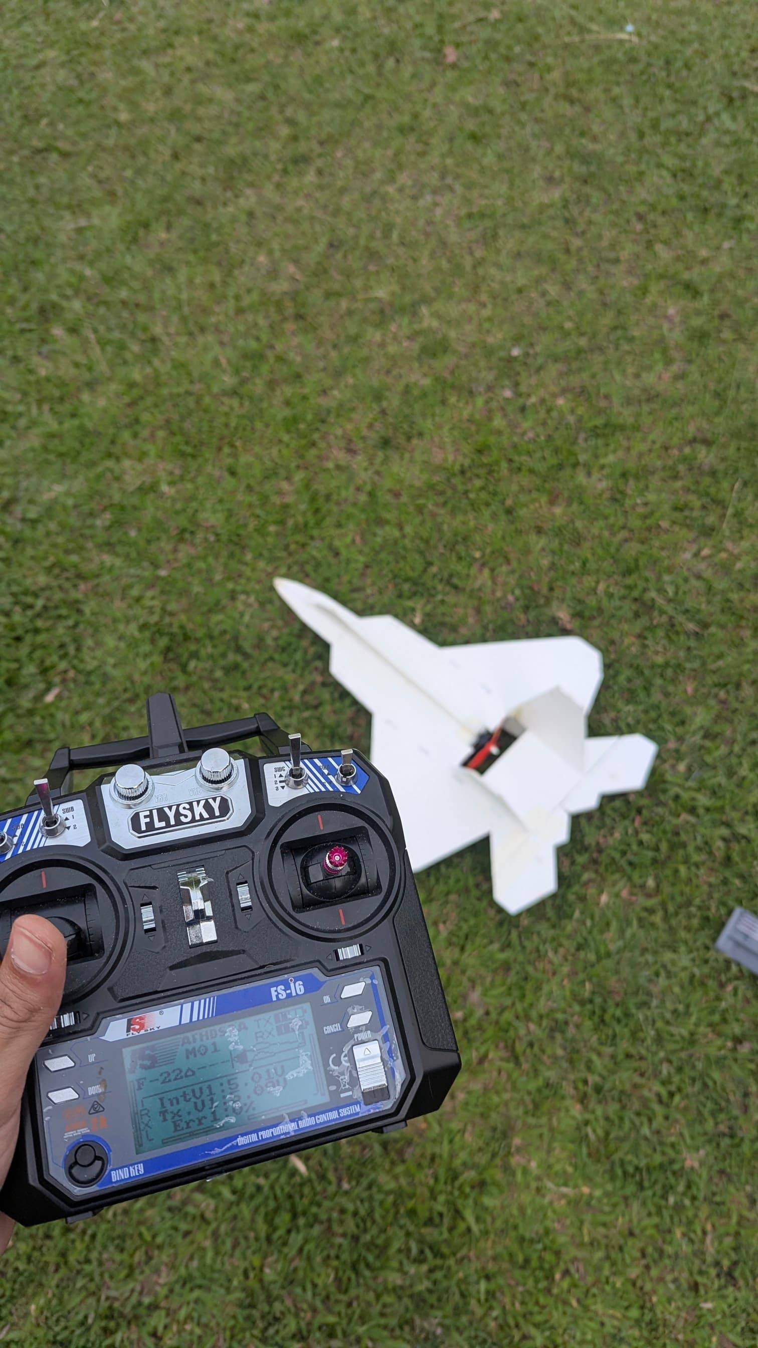
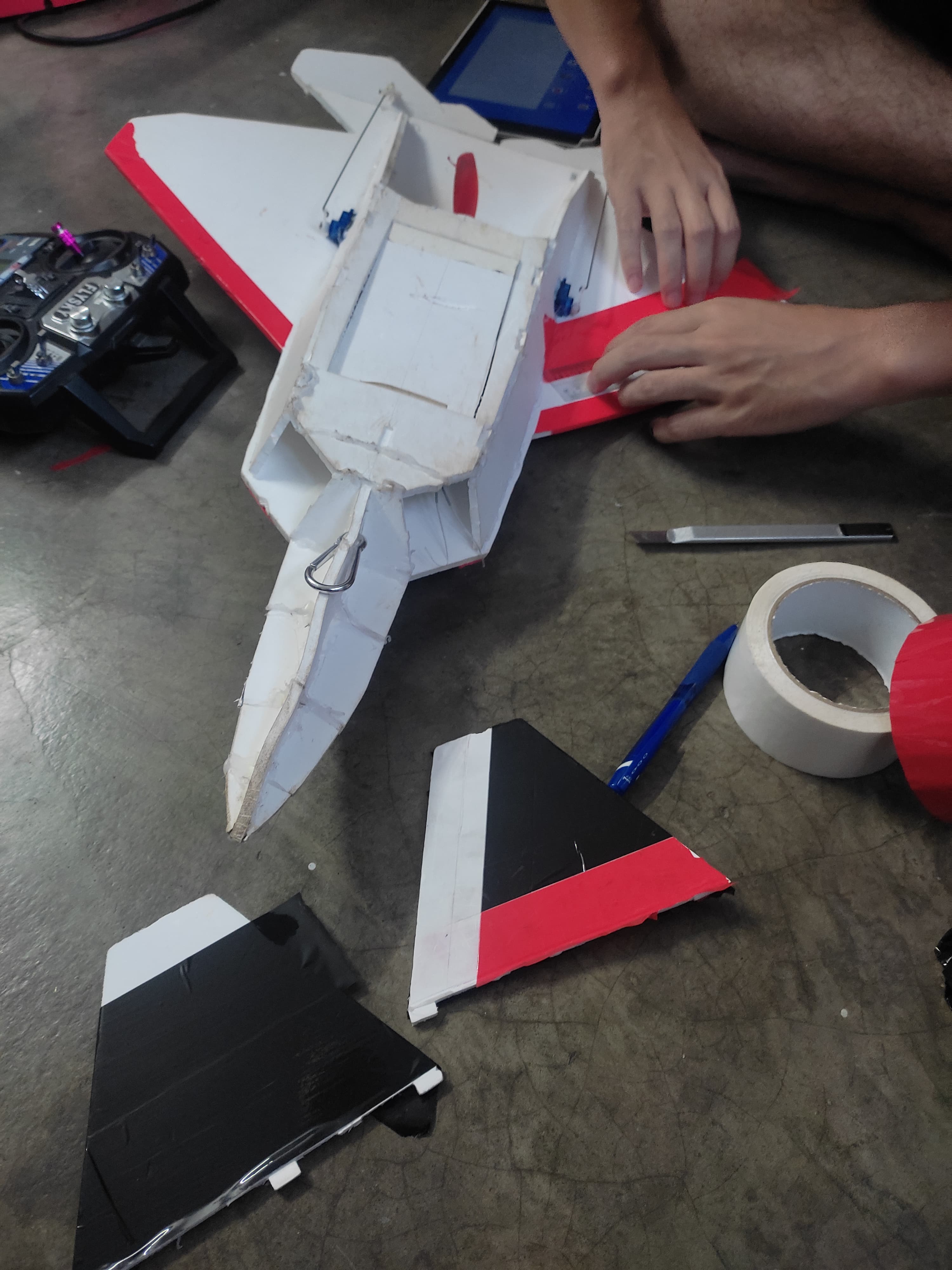
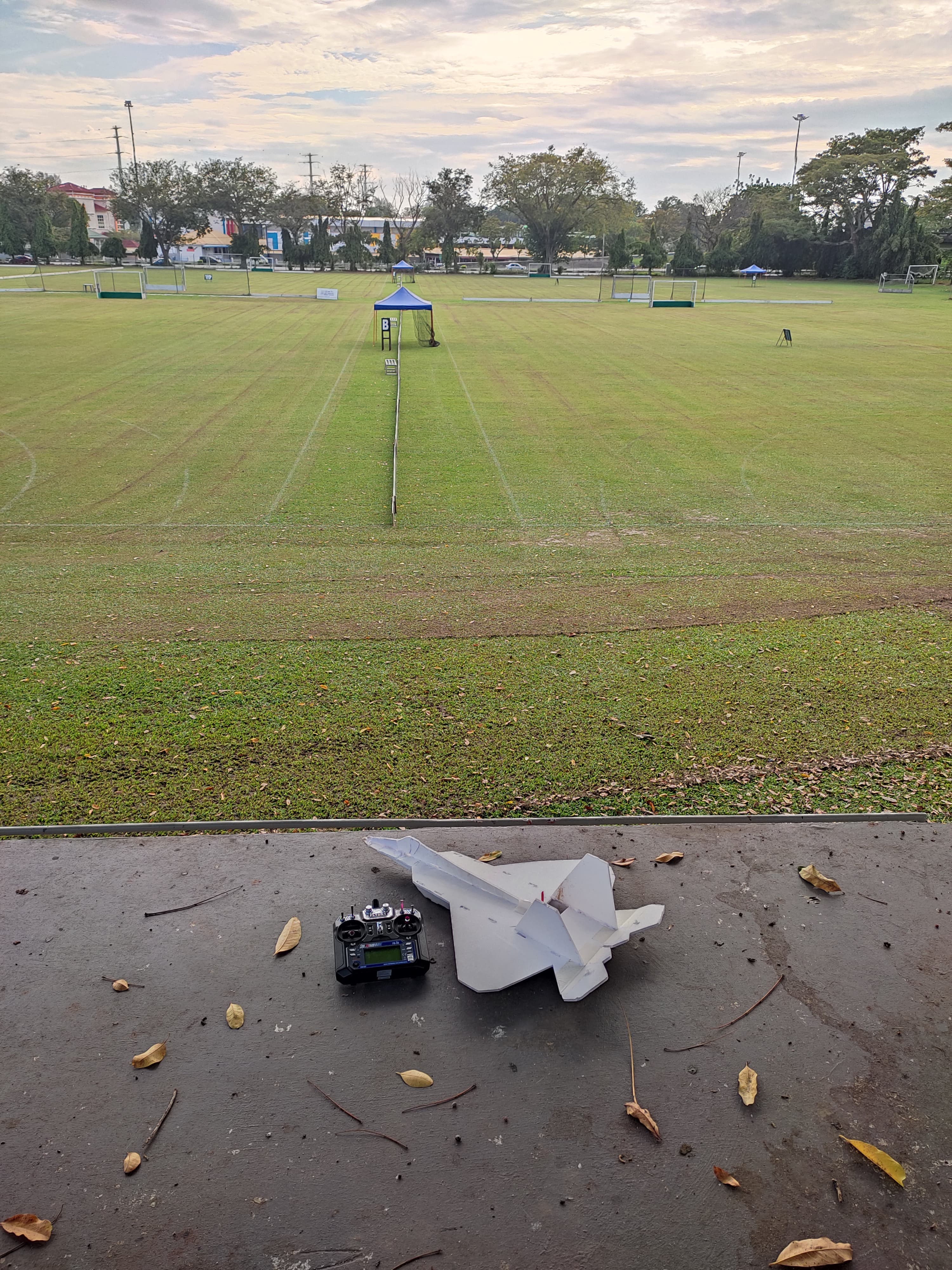
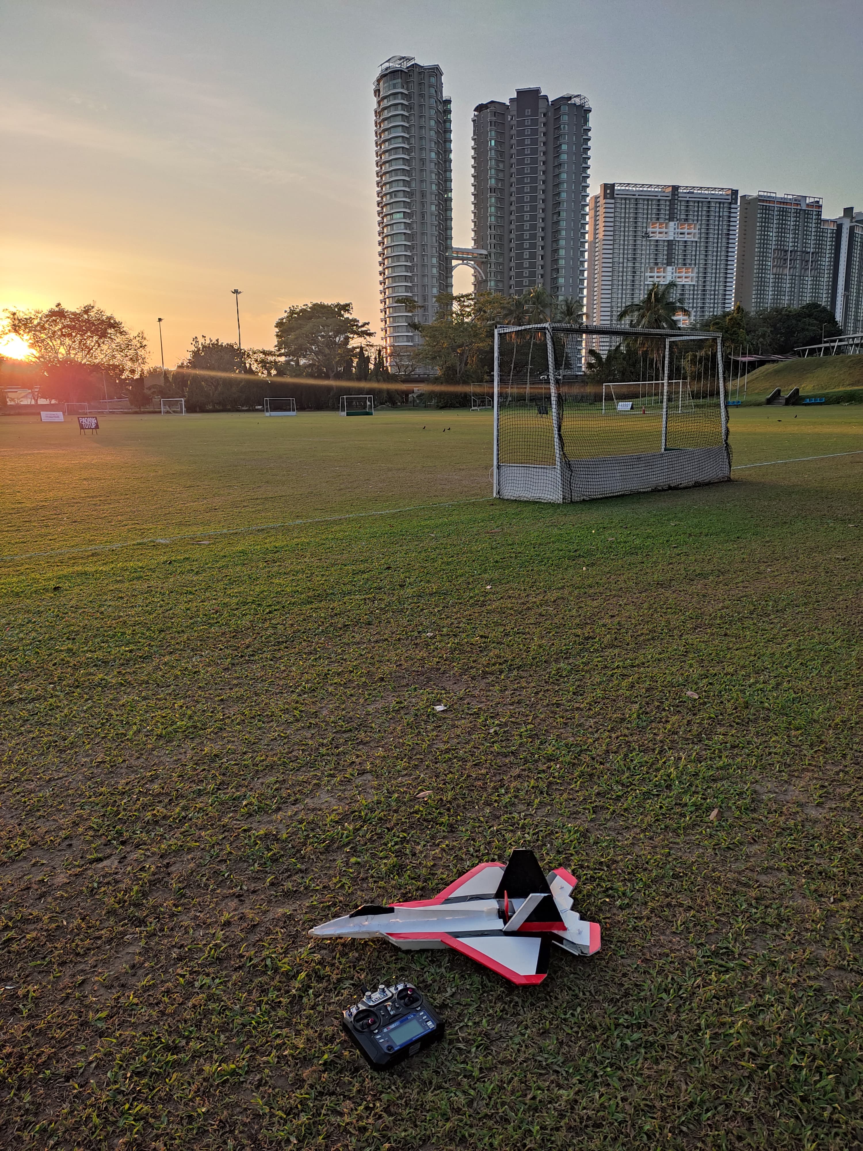
Gallery
Build photos and flight footage
What I Learned
Key takeaways and insights
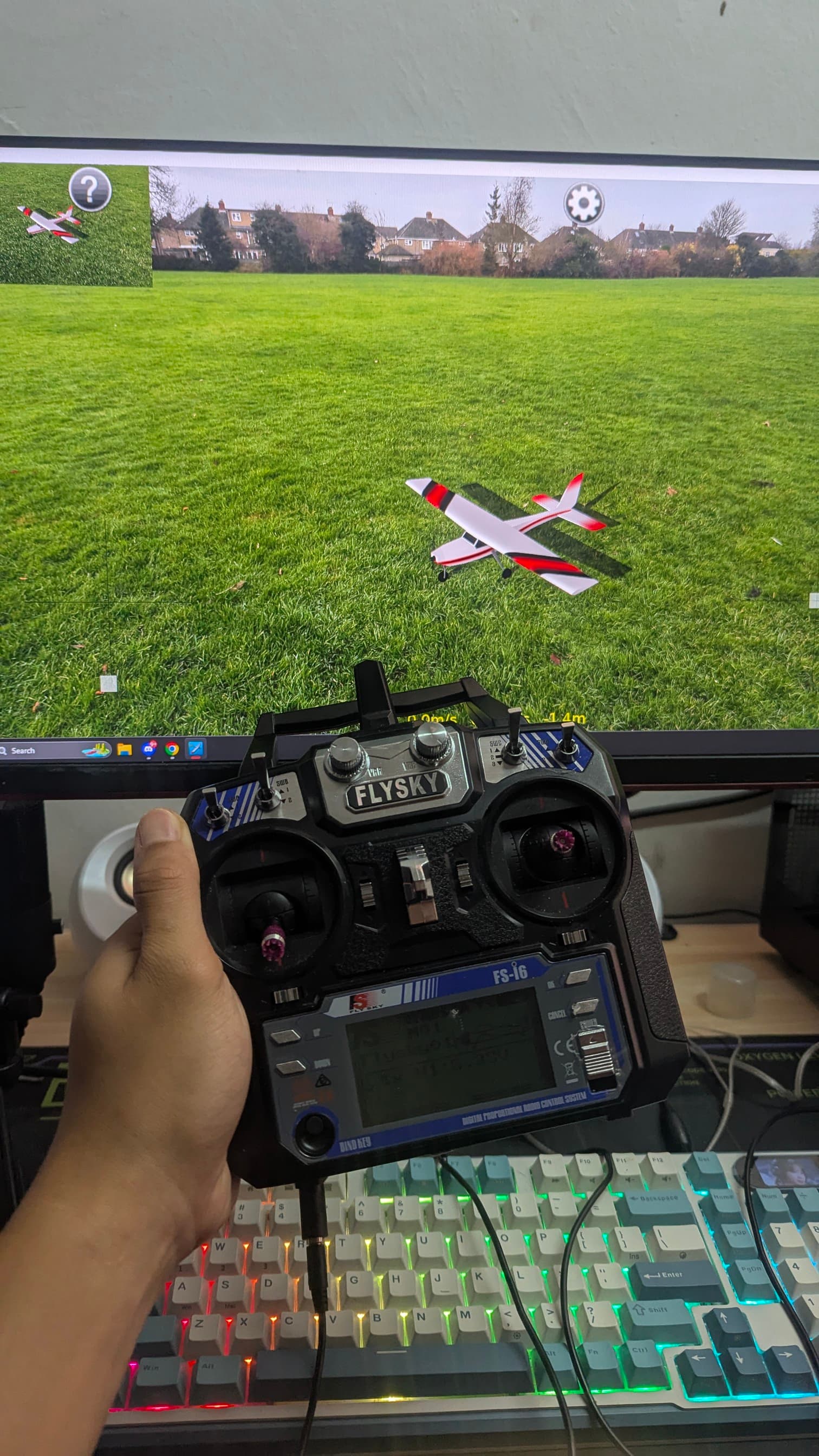
Lesson 1: Simulation is cheaper compared to real-world testing. (learned that the hard way)
Lesson 2: Take time with the build - dont get too excited and rush.
Lesson 3: Test electronics thoroughly before final assembly. Disassembling is time-consuming.
Lesson 4: Weather plays a significant role in flight performance and safety.
Lesson 5 (most important): Never give up. Crashing is part of it. I literally crashed 7 times before succeeding :D. Find out what's wrong, improvise, forget how much it hurts, and try again.
Resources
Helpful links and references